Lattice Girders, Steel Arches & Props
DSI Underground Canada selection of underground supports, the widest in the world, affords the contractor, the designer, and the owner a matchless combination of high performance and tunneling at low cost. One of these products alone - liner plates - offers these outstanding advantages:
- Economy of construction in time, excavation, material, manpower.
- Maximum support per given length with minimum weight of steel.
- Standard variation of plate design for all shapes of tunnels in dry or wet ground.
- Predictable strength, fire resistant.
- Continuous support during the critical mining phase in soft ground tunneling.
- Easy to store, handle and erect, whether the tunnel is straight, curved, circular, elliptical or horseshoe in shape.
- Gasket plates that seal joints, stop water leakage and reduce air loss when water is a problem.

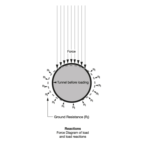
There are various methods for determining the required strength of tunnel linings. Nevertheles, the type of ground, the location and depth of cover, the size and length of the tunnel, level of ground water, superimposed loading, and history always guide these calculations.

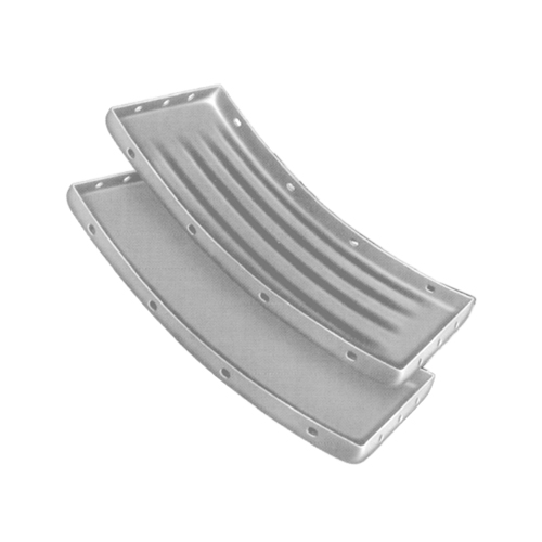
DSI Underground's liner plates can be purchased in 16" and 24" widths as corrugated or smooth plates. Liner plates are formed from one piece of metal to provide longitudinal and circumferential flanges. The plates can be galvanized and/or bituminously coated and grout holes with plugs can be included. For special conditions gasketed liner plates and tapered liner plates can also be manufactured. Liner plates can be installed alone or in conjunction with steel ribs if additional support is required.
General Specifications
The following paragraphs are offered as a guide for those who write and issue specifications for steel liner plates as underground supports.
Scope
These specifications are intended to cover the fabrication and installation of liner plates in tunnels constructed by conventional methods. Tunnels excavated by full face, heading and bench, or multiple drift procedures are considered conventional methods. Liner plates used with any construction method utilizing a full or partial shield, a tunneling machine, or other equipment which will exert a force upon the liner plates to propel, steer, or stabilize the equipment are considered special cases and are not covered by these specifications.
Material Specifications
Thickness tolerances shall conform to AASHTO specification for Highway Bridges, Section 16, or comparable AREMA Manual for Railway Engineering, Chapter 1, Section 4~15.
The Tunnel Liner Plates shall be fabricated from structural quality, hot rolled, carbon steel sheets or plates conforming to the specification of ASTM designation A1011.
The mechanical properties of the flat plate and sheets before cold forming shall be:
Tensile Strength psi 42,000 Min.
Yield Strength psi 28,000 Min.
Elongation in 2 inches, % 30 Min
Description
Cold-formed steel liner plates conforming to the specifications below shall be furnished to the sizes and dimensions required on the plans. Such plates shall be installed at the locations designated on the plans or as designed by the engineer or the responsible authority.
Design and shape of the liner plates shall be such that erection and assembly of the liner plate structure can be completely and readily erected from inside the tunnel.
Plates shall be accurately curved to suit the tunnel cross section, and all dimensions are of such size and accuracy that plates of similar curvature will be interchangeable.
Bolts on both the longitudinal and circumferential joints shall connect all plates.
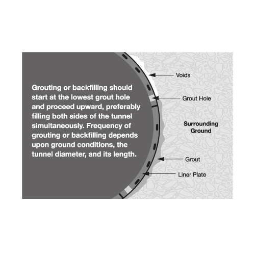
Grout holes 2 inches in diameter shall be provided, as shown on the plans, to permit grouting as the erection of tunnel liner plates proceeds.

Forming and Punching of Liner Plates
All plates shall be formed from one piece of metal to provide longitudinal and circumferential flanges. They shall be punched for bolting on both longitudinal and circumferential flanges in accordance with the manufacturer's standard spacing, and shall be a multiple of the plate length so that plates having the same curvature shall be interchangeable and will permit staggering of the joints.Grout holes with plugs shall be provided at spacing sufficient to allow filling of all voids with grouting material.
Galvanizing and Coating
Where liner plates are used as temporary supports, and the permanent support is monolithic concrete or reinforced concrete pipe, and the opening between the back of the pipe and the inside of the liner plate is filled with grout or sand, liner plates are furnished black, not coated.
When so specified, the liner plates will be galvanized to meet the current ASTM Specification A 123. In addition, the liner plates when so specified, shall be bituminous coated to meet the current AASHTO Specification M190.
Bolts and Nuts
Bolts and nuts used with four-flange liner plates shall be not less than 1/2 inch diameter for 7 gage plates and lighter, and not less than 5/8 inch diameter for liner plates heavier than 7 gage. They shall be quickacting coarse thread with material conforming to ASTM Specification A307.
When required, the bolts and nuts shall be hot dip galvanized to conform to ASTM Specification A 153.
Installation
Liner plates shall be assembled in accordance with the manufacturer's instructions. Voids occurring between the liner plates and the surrounding ground shall be pressure grouted as directed by the engineer in charge to completely fill all voids. The grout shall be forced through the grouting holes provided in the liner plates.

